2026-10-10
Elevation, outline, centreline: how to read a technical drawing
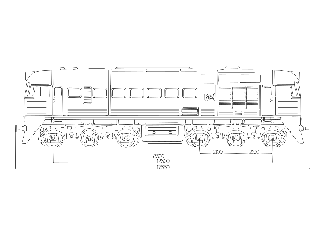
When you see a locomotive or truck as a line drawing, three things set it apart from a photograph: it is viewed exactly from the side, only outlines are drawn, and the wheel centres are marked. Each has a name.
A side elevation (also called a profile view) is an orthographic projection: the vehicle is seen exactly from the side, with no perspective. Near and far parts keep the same size, so lengths can be compared directly. On the M62 drawing the rail level is a horizontal line, and the cabs and engine bay follow each other in a straight row.
An outline drawing (or line drawing) shows only the contours and the important inner edges, with no shading or texture. Plotters love it: one line, one pen stroke. When dimensions are added it becomes a dimensioned drawing, which is what the M62 image is: the three horizontal dimension lines give the axle spacing, the bogie spacing and the overall length.
The centreline is the third term. Wheels, axles and holes are rotationally symmetric, so a technical drawing marks their centre with a long-short dashed line. It is not part of the object but a guide: axle spacings are measured from it and dimension lines attach to it. If you see a dashed mark through the middle of each wheel, that is the centreline. On the M62 drawing, the dimension lines dropping from the wheel centres do the same job.
If you are searching for similar pictures, try: side elevation line drawing, orthographic side view, dimensioned drawing, centreline. The white-on-blue version is called a blueprint, but that names a style, not a view.
Every train in the gallery is such a side-elevation drawing. Pick one and we draw it with pen on paper.